
ST7789 TFT 显示屏驱动
1. 简介
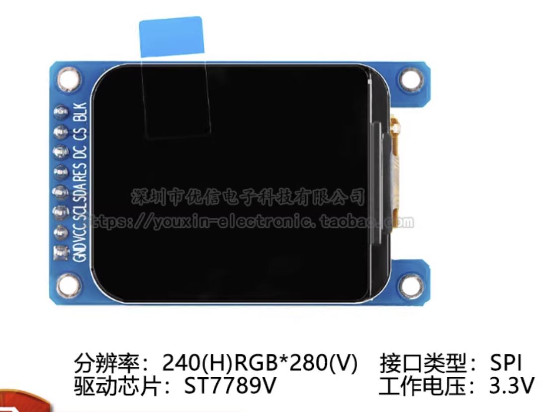
ST7789 是一种低成本、低功耗的 TFT-LCD 显示屏驱动器,广泛应用于各种嵌入式设备和物联网设备中。它支持多种分辨率和颜色深度,具有高对比度、宽视角和快速响应等特点,适用于各种应用场景。
2. 功能特点
- 支持 240x240 和 240x320 两种分辨率,240x280 实际上是从240x320上裁剪而来的,并不算是一种分辨率.
- 支持 16 位和 18 位颜色深度,一般用16位色
- 支持多种显示模式,包括正常模式、
- 支持四个方向翻转模式、上下翻转模式和左右翻转模式
- 支持多种时序模式,包括标准时序和低功耗时序
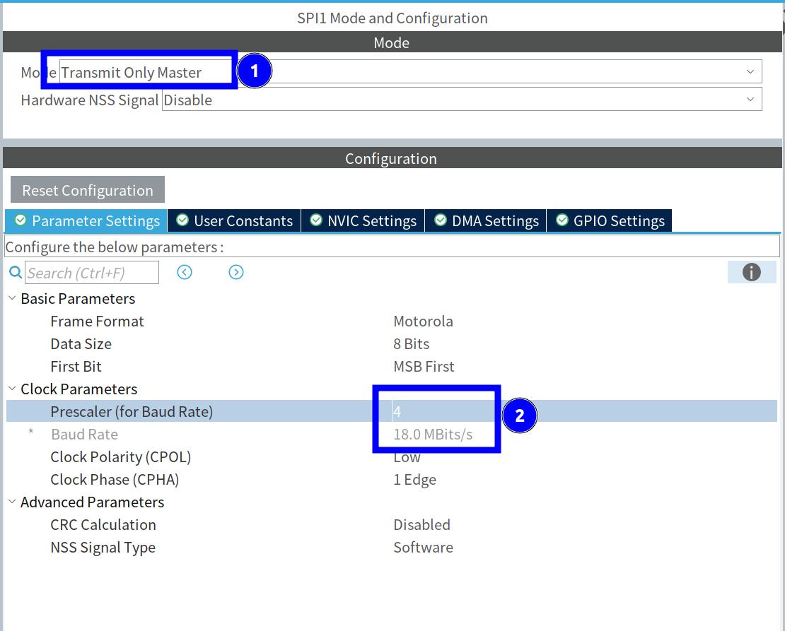
- 支持多种接口,包括 SPI 和并行接口
- 支持多种命令,包括显示控制命令、窗口设置命令和颜色设置命令等
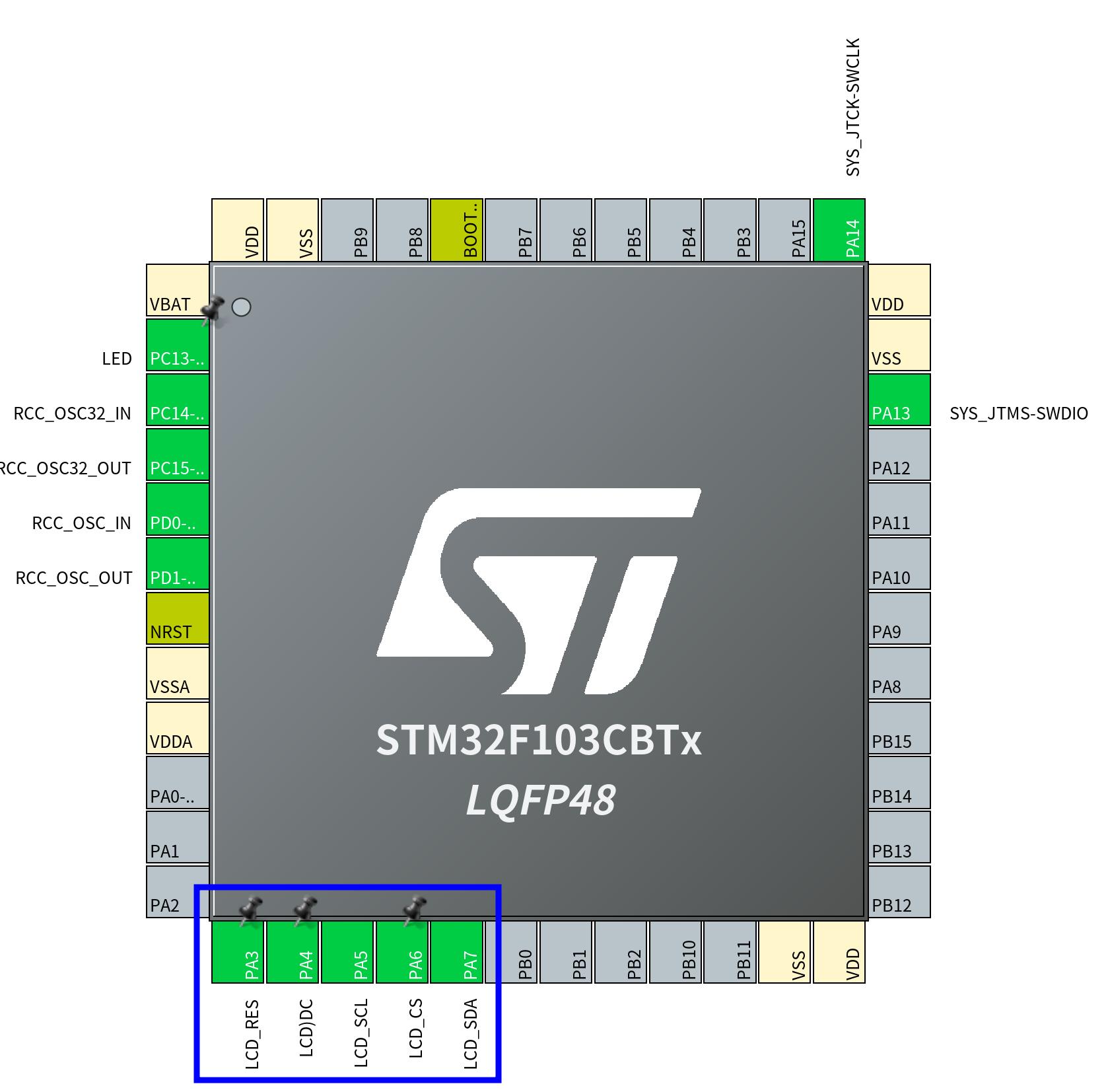
3. 接口说明
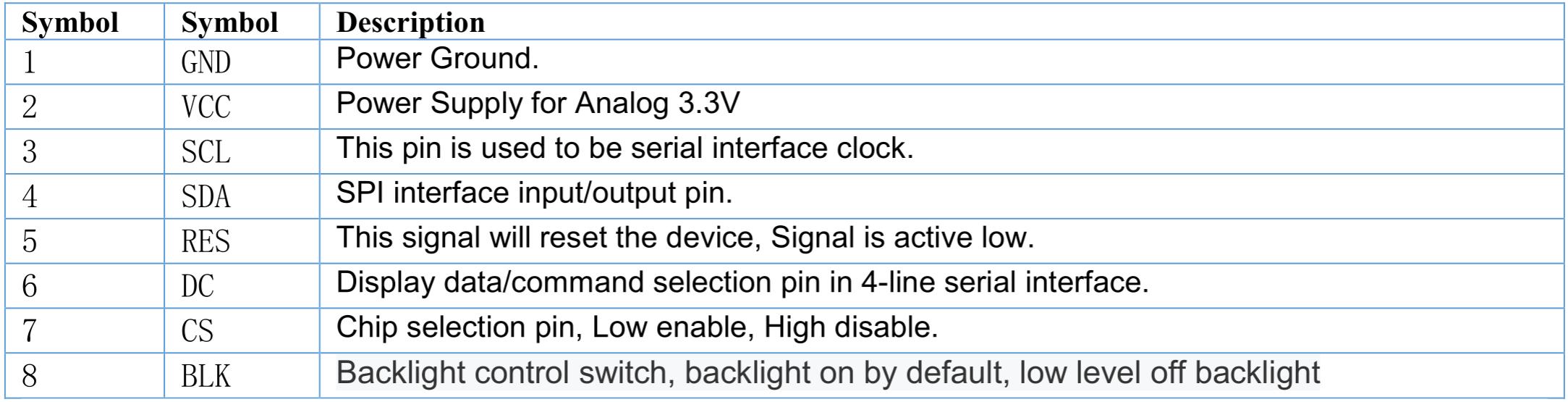
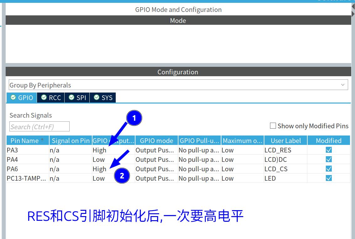
注意:
LCD_RES,LCD_CS引脚在初始化GPIO后,一定要设置为 高电平 ,因为在初始化代码中,会先将LCD_RES引脚设置为低电平,然后再设置为高电平.
4. 驱动代码
(1) 初始化代码
void LCD_Init(void)
{

    // 复位
    HAL_GPIO_WritePin(LCD_RES_GPIO_Port, LCD_RES_Pin, GPIO_PIN_RESET);
    HAL_Delay(200);
    HAL_GPIO_WritePin(LCD_RES_GPIO_Port, LCD_RES_Pin, GPIO_PIN_SET);
    HAL_Delay(200);

    // Sleep out
    tft_write_cmd(0x11);
    HAL_Delay(200);

    // Memory Access Control
    tft_write_cmd(0x36);
    tft_write_data(0x00);  // 竖屏模式 ,16位色 (RGB565)

    // Pixel Format Set - 16位色
    tft_write_cmd(0x3A);
    tft_write_data(0x55);

    // 额外添加:确保显示 inversion 和 display on
    tft_write_cmd(0x21);   // Display Inversion On
    HAL_Delay(10);

    // Porch Setting - 5个参数
    tft_write_cmd(0xB2);
    tft_write_data(0x0C);
    tft_write_data(0x0C);
    tft_write_data(0x00);
    tft_write_data(0x33);
    tft_write_data(0x33);

    // VCOM Control 1
    tft_write_cmd(0xB7);
    tft_write_data(0x35);

    // VCOM Control 2
    tft_write_cmd(0xBB);
    tft_write_data(0x32);

    // NVMEM Control
    tft_write_cmd(0xC2);
    tft_write_data(0x01);

    // VRH Control
    tft_write_cmd(0xC3);
    tft_write_data(0x15);

    // VDV Control
    tft_write_cmd(0xC4);
    tft_write_data(0x20);

    // Frame Rate Control
    tft_write_cmd(0xC6);
    tft_write_data(0x0F);

    // Power Control 1
    tft_write_cmd(0xD0);
    tft_write_data(0xA4);
    tft_write_data(0xA1);

    // Positive Voltage Gamma Control - 14个参数
    tft_write_cmd(0xE0);
    tft_write_data(0xD0);
    tft_write_data(0x08);
    tft_write_data(0x0E);
    tft_write_data(0x09);
    tft_write_data(0x09);
    tft_write_data(0x05);
    tft_write_data(0x31);
    tft_write_data(0x33);
    tft_write_data(0x48);
    tft_write_data(0x17);
    tft_write_data(0x14);
    tft_write_data(0x15);
    tft_write_data(0x31);
    tft_write_data(0x34);

    // Negative Voltage Gamma Control - 14个参数
    tft_write_cmd(0xE1);
    tft_write_data(0xD0);
    tft_write_data(0x08);
    tft_write_data(0x0E);
    tft_write_data(0x09);
    tft_write_data(0x09);
    tft_write_data(0x15);
    tft_write_data(0x31);
    tft_write_data(0x33);
    tft_write_data(0x48);
    tft_write_data(0x17);
    tft_write_data(0x14);
    tft_write_data(0x15);
    tft_write_data(0x31);
    tft_write_data(0x34);

    // Display ON
    tft_write_cmd(0x29);
    HAL_Delay(500);
}注意看清楚: 这里的初始化代码是区分命令和数据的顺序的,先发命令再发数据,不能全部当成数据发送.因为发送命令的时候,DC引脚的状态是不一样的.
(2) 重点代码说明
    tft_write_cmd(0x36);
    tft_write_data(0x00);  // 竖屏模式 ,RGB字节顺序
这个代码用于设置显示模式为竖屏模式,并选择16位色。其中,0x36 是设置内存访问控制寄存器的命令,0x00 是设置参数,表示竖屏模式和16位色。 RGB字节顺序表示用16位来表示颜色的话,是按 RGB 的顺序来排列的. 还有一种是按 BGR 的顺序来排列的. 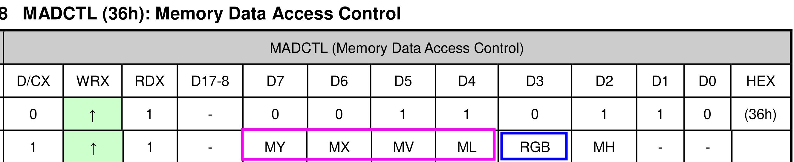
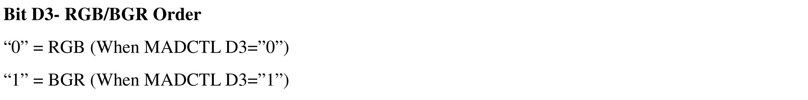 当0x36 的第 4 位为 0 时,表示按RBG的顺序排列.否则是按BGR的顺序排列. 其它的几个位决定了数据发送的顺序, 比如: 0x36 的第 7 位表示数据发送的顺序, 设置为 0x00,表示数据按从左向右,从下向下的顺序,布置于屏幕上.
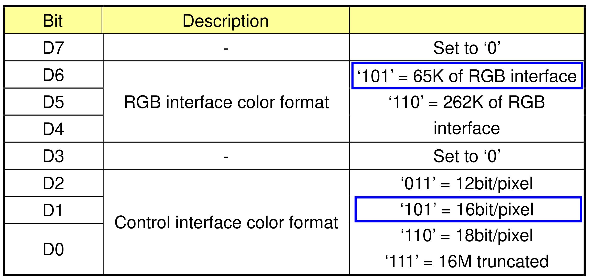
    tft_write_cmd(0x3A);
    tft_write_data(0x55);
这个代码用于设置像素格式为16位色。其中,0x3A 是设置像素格式寄存器的命令,0x55 是设置参数,表示64K颜色 16位色。 这里知道了是16位色,那么一个字节就可以表示一个颜色值,按 5654 的顺序排列, 也就是 5位表示红色R,6位表示绿色G,5位表示蓝色B. 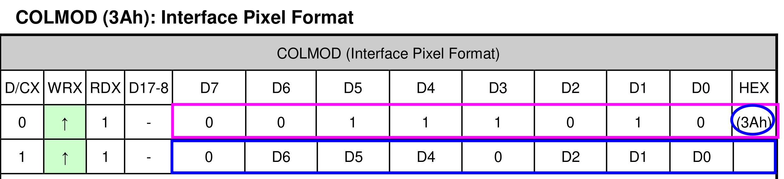
 其它的初始化代码,可以参考 ST7789 的数据手册,根据需要设置.
5. TFT显示逻辑
- ST7789的显示与SSD1306完全不同,SSD1306属于单色的显示器,他一个位就可以表示一个像素点,而ST7789是一个16位色显示器,两个字节就可以表示一个像素点.所以它不需要分页,而是一个像素一个像素的发送数据.
- 它显示时,首先要指定显示的区域,然后发送数据. 所有发送的数据,全部辅满整个显示区域.
void LCD_Address_Set(uint16_t x,uint16_t y,uint16_t w,uint16_t h)
{
    tft_write_cmd(0x2A); //写x坐标
    tft_write_data16(x);
    tft_write_data16(x+w-1);
    tft_write_cmd(0x2B); //写y坐标
    tft_write_data16(y+20);
    tft_write_data16(y+h+20);
    tft_write_cmd(0x2C); //写数据
}
这个函数的作用就是设置操作区域,指定坐标位置及大小. 这里的 y 坐标加了 20 个像素 . 因为这个显示器实际上是从 240320 的分辨率上进行 裁剪的,所以实际显示的区域是 240280. 这里的 y 坐标加了 20 个像素,是因为这个显示器实际上从 240*320 的分辨率开始,所以 y 坐标从 20 开始. 结束区域后面还有20个像素未使用,共有 40个像素,也就是 320 - 280 = 40.
void LCD_Clear(uint16_t Color)
{
    uint32_t i;
    LCD_Address_Set(0,0,240,280);
    for(i=0;i<240*280;i++)
    {
        tft_write_data16(Color);
    }
}
这个函数的作用就是清屏,将整个屏幕的像素点全部设置为指定的颜色.
6. 显示内容
LCD_Init();

  while (1) {
    LCD_Clear(0xF800); // 红色
    HAL_Delay(500);
    LCD_Clear(0x07E0); // 绿色
    HAL_Delay(500);
    LCD_Clear(0x001F); // 蓝色
    HAL_Delay(500);
  }
这个程序首先初始化 LCD,然后清屏,显示红色,等待500ms,再清屏,显示绿色,等待500ms,再清屏,显示蓝色,等待500ms,重复这个过程.
7. 完整代码
#ifndef __TFT_H__
#define __TFT_H__

#define TFT_WIDTH  240
#define TFT_HEIGHT 280  // ST7789通常是280行

void LCD_Init(void);
void LCD_Address_Set(uint16_t x,uint16_t y,uint16_t w,uint16_t h);
void LCD_Fill(uint16_t x,uint16_t y,uint16_t w,uint16_t h,uint16_t color);
void LCD_Fill_Fast(uint16_t x,uint16_t y,uint16_t w,uint16_t h,uint16_t color);
void LCD_Clear(uint16_t color);

#endif /* __TFT_H__ */#include "spi.h"
#include "gpio.h"
#include "tft.h"
#include "main.h"
// 前向声明
static void tft_write_cmd(uint8_t cmd);
static void tft_write_data(uint8_t data);
static void tft_write_data16(uint16_t data);
// 性能优化说明:
// 原始方案:每个像素调用2次HAL_SPI_Transmit,240*280=134400次函数调用
// 优化方案1(LCD_Fill_Fast):使用512字节缓冲区,仅需约263次传输,速度提升约500倍
// 优化方案2(LCD_Fill):使用DMA+1KB缓冲区,非阻塞传输,CPU可执行其他任务
// 建议选择:LCD_Fill_Fast(简单高效)或LCD_Fill(DMA异步,适合复杂应用)
// 正确的ST7789初始化函数
void LCD_Init(void)
{
// 复位
HAL_GPIO_WritePin(LCD_RES_GPIO_Port, LCD_RES_Pin, GPIO_PIN_RESET);
HAL_Delay(200);
HAL_GPIO_WritePin(LCD_RES_GPIO_Port, LCD_RES_Pin, GPIO_PIN_SET);
HAL_Delay(200);
// Sleep out
tft_write_cmd(0x11);
HAL_Delay(200);
// Memory Access Control
tft_write_cmd(0x36);
tft_write_data(0x00); // 竖屏模式 ,16位色 (RGB565)
// Pixel Format Set - 16位色
tft_write_cmd(0x3A);
tft_write_data(0x55);
// 额外添加:确保显示 inversion 和 display on
tft_write_cmd(0x21); // Display Inversion On
HAL_Delay(10);
// Porch Setting - 5个参数
tft_write_cmd(0xB2);
tft_write_data(0x0C);
tft_write_data(0x0C);
tft_write_data(0x00);
tft_write_data(0x33);
tft_write_data(0x33);
// VCOM Control 1
tft_write_cmd(0xB7);
tft_write_data(0x35);
// VCOM Control 2
tft_write_cmd(0xBB);
tft_write_data(0x32);
// NVMEM Control
tft_write_cmd(0xC2);
tft_write_data(0x01);
// VRH Control
tft_write_cmd(0xC3);
tft_write_data(0x15);
// VDV Control
tft_write_cmd(0xC4);
tft_write_data(0x20);
// Frame Rate Control
tft_write_cmd(0xC6);
tft_write_data(0x0F);
// Power Control 1
tft_write_cmd(0xD0);
tft_write_data(0xA4);
tft_write_data(0xA1);
// Positive Voltage Gamma Control - 14个参数
tft_write_cmd(0xE0);
tft_write_data(0xD0);
tft_write_data(0x08);
tft_write_data(0x0E);
tft_write_data(0x09);
tft_write_data(0x09);
tft_write_data(0x05);
tft_write_data(0x31);
tft_write_data(0x33);
tft_write_data(0x48);
tft_write_data(0x17);
tft_write_data(0x14);
tft_write_data(0x15);
tft_write_data(0x31);
tft_write_data(0x34);
// Negative Voltage Gamma Control - 14个参数
tft_write_cmd(0xE1);
tft_write_data(0xD0);
tft_write_data(0x08);
tft_write_data(0x0E);
tft_write_data(0x09);
tft_write_data(0x09);
tft_write_data(0x15);
tft_write_data(0x31);
tft_write_data(0x33);
tft_write_data(0x48);
tft_write_data(0x17);
tft_write_data(0x14);
tft_write_data(0x15);
tft_write_data(0x31);
tft_write_data(0x34);
// Display ON
tft_write_cmd(0x29);
HAL_Delay(500);
}
// uint8_t InitCode[]= {
// 0x36, 0x00, // Memory Access Control
// 0x3A, 0x05, // Pixel Format Set
// 0xB2, 0x0C, 0x0C, 0x00, 0x33, 0x33, // Porch Setting
// 0xB7, 0x35, // VCOM Control 1
// 0xBB, 0x32, // VCOM =1.35
// 0xC2, 0x01,
// 0xC3, 0x15,
// 0xC4, 0x20,
// 0xC6, 0x0F,
// 0xD0, 0xA4, 0xA1,
// 0xE0, 0xD0, 0x08, 0x0E, 0x09, 0x09, 0x05, 0x31, 0x33, 0x48, 0x17, 0x14, 0x15, 0x31, 0x34,
// 0xE1, 0xD0, 0x08, 0x0E, 0x09, 0x09, 0x15, 0x31, 0x33, 0x48, 0x17, 0x14, 0x15, 0x31, 0x34,
// 0x21, // Inversion On
// // Add more initialization commands as needed
// };
static void tft_write_cmd(uint8_t cmd)
{
HAL_GPIO_WritePin(LCD_DC_GPIO_Port, LCD_DC_Pin, GPIO_PIN_RESET); // Command mode
HAL_GPIO_WritePin(LCD_CS_GPIO_Port, LCD_CS_Pin, GPIO_PIN_RESET); // Select the LCD
HAL_SPI_Transmit(&hspi1, &cmd, 1, HAL_MAX_DELAY);
HAL_GPIO_WritePin(LCD_CS_GPIO_Port, LCD_CS_Pin, GPIO_PIN_SET); // Deselect the LCD
// 不强制设置DC为高,保持当前状态
}
static void tft_write_data(uint8_t data)
{
HAL_GPIO_WritePin(LCD_DC_GPIO_Port, LCD_DC_Pin, GPIO_PIN_SET); // Data mode
HAL_GPIO_WritePin(LCD_CS_GPIO_Port, LCD_CS_Pin, GPIO_PIN_RESET); // Select the LCD
HAL_SPI_Transmit(&hspi1, &data, 1, HAL_MAX_DELAY);
HAL_GPIO_WritePin(LCD_CS_GPIO_Port, LCD_CS_Pin, GPIO_PIN_SET); // Deselect the LCD
}
static void tft_write_data16(uint16_t data)
{
uint8_t high_byte = (data >> 8) & 0xFF;
uint8_t low_byte = data & 0xFF;
HAL_GPIO_WritePin(LCD_DC_GPIO_Port, LCD_DC_Pin, GPIO_PIN_SET); // Data mode
HAL_GPIO_WritePin(LCD_CS_GPIO_Port, LCD_CS_Pin, GPIO_PIN_RESET); // Select the LCD
// 发送顺序:先高字节后低字节(标准做法)
HAL_SPI_Transmit(&hspi1, &high_byte, 1, HAL_MAX_DELAY);
HAL_SPI_Transmit(&hspi1, &low_byte, 1, HAL_MAX_DELAY);
HAL_GPIO_WritePin(LCD_CS_GPIO_Port, LCD_CS_Pin, GPIO_PIN_SET); // Deselect the LCD
}
void LCD_Address_Set(uint16_t x,uint16_t y,uint16_t w,uint16_t h)
{
tft_write_cmd(0x2A); //写x坐标
tft_write_data16(x);
tft_write_data16(x+w-1);
tft_write_cmd(0x2B); //写y坐标
tft_write_data16(y+20);
tft_write_data16(y+h+20);
tft_write_cmd(0x2C); //写数据
}
// 优化的快速填充函数 - 使用缓冲区批量传输
// 优化版:使用阻塞式批量传输(推荐,避免DMA配置问题)
void LCD_Fill(uint16_t x, uint16_t y, uint16_t w, uint16_t h, uint16_t color)
{
uint32_t num_pixels = (uint32_t)w * h;
uint8_t color_high = (color >> 8) & 0xFF;
uint8_t color_low = color & 0xFF;
LCD_Address_Set(x, y, w, h); // 设置显示区域
// 设置DC为数据模式,CS选中
HAL_GPIO_WritePin(LCD_DC_GPIO_Port, LCD_DC_Pin, GPIO_PIN_SET);
HAL_GPIO_WritePin(LCD_CS_GPIO_Port, LCD_CS_Pin, GPIO_PIN_RESET);
// 使用较大的缓冲区批量发送(1KB)
#define BUFFER_SIZE 1024
uint8_t spi_buffer[BUFFER_SIZE];
// 填充缓冲区
for (int i = 0; i < BUFFER_SIZE; i += 2) {
spi_buffer[i] = color_high;
spi_buffer[i + 1] = color_low;
}
// 批量发送数据
uint32_t bytes_to_send = num_pixels * 2; // 每个像素2字节
// 如果数据量小,直接发送
if (bytes_to_send <= BUFFER_SIZE) {
HAL_SPI_Transmit(&hspi1, spi_buffer, bytes_to_send, HAL_MAX_DELAY);
} else {
// 大数据量:分批发送
while (bytes_to_send > 0) {
uint16_t chunk_size = (bytes_to_send > BUFFER_SIZE) ? BUFFER_SIZE : bytes_to_send;
HAL_SPI_Transmit(&hspi1, spi_buffer, chunk_size, HAL_MAX_DELAY);
bytes_to_send -= chunk_size;
}
}
HAL_GPIO_WritePin(LCD_CS_GPIO_Port, LCD_CS_Pin, GPIO_PIN_SET);
}
// 阻塞式快速版本 - 不使用DMA,但使用批量传输
void LCD_Fill_Fast(uint16_t x, uint16_t y, uint16_t w, uint16_t h, uint16_t color)
{
uint32_t num_pixels = (uint32_t)w * h;
uint8_t color_high = (color >> 8) & 0xFF;
uint8_t color_low = color & 0xFF;
LCD_Address_Set(x, y, w, h); // 设置显示区域
// 设置DC为数据模式,CS选中
HAL_GPIO_WritePin(LCD_DC_GPIO_Port, LCD_DC_Pin, GPIO_PIN_SET);
HAL_GPIO_WritePin(LCD_CS_GPIO_Port, LCD_CS_Pin, GPIO_PIN_RESET);
// 使用较大的缓冲区批量发送
#define FAST_BUFFER_SIZE 512
uint8_t fast_buffer[FAST_BUFFER_SIZE];
// 填充缓冲区
for (int i = 0; i < FAST_BUFFER_SIZE; i += 2) {
fast_buffer[i] = color_high;
fast_buffer[i + 1] = color_low;
}
// 批量发送数据
uint32_t bytes_to_send = num_pixels * 2; // 每个像素2字节
while (bytes_to_send > 0) {
uint16_t chunk_size = (bytes_to_send > FAST_BUFFER_SIZE) ? FAST_BUFFER_SIZE : bytes_to_send;
HAL_SPI_Transmit(&hspi1, fast_buffer, chunk_size, HAL_MAX_DELAY);
bytes_to_send -= chunk_size;
}
HAL_GPIO_WritePin(LCD_CS_GPIO_Port, LCD_CS_Pin, GPIO_PIN_SET);
}
void LCD_Clear(uint16_t color){
LCD_Fill(0,0,TFT_WIDTH,TFT_HEIGHT,color);
}如何进一步提升性能
目前使用缓冲区的方法可以大幅度提升性能,但仍有优化空间。 因为一个字节一个字节的传输数据,每一次小的传输都会产生一些准备和收尾的动作.这里动作所消耗的时间相比传输时间是非常可观的. 当我们采用批量传输数据的方法时, 我们可以一次性传输多个字节或者字,从而减少这些准备和收尾动作所消耗的时间. 这个提升是很明显的. 但也是有代价的.就是会占用更多的内存.
DMA传输:DMA传输是一种硬件加速技术,可以减少CPU的负担,提高数据传输速度。其实DMA传输提升的传输速度是很有限的,但是可以节省CPU资源, 这在进行双缓冲时, DMA传输可以提升性能. 数据在传输过程中,CPU就可以去准备下一个数据, 避免了CPU等待DMA传输完成.